

In the complex landscape of hydraulic engineering and industrial fluid transfer, the gear pump for oil stands as a cornerstone of mechanical efficiency. Unlike more intricate piston or vane designs, this pump type relies on the elegant simplicity of two interlocking gears rotating within a precision-machined housing. This fundamental design, while deceptively straightforward, is the primary driver for lubrication systems, fuel delivery networks, and power transmission units across heavy industry, agricultural machinery, and automotive manufacturing.
Understanding the mechanics and the appropriate application of these systems is vital for maintenance engineers and facility managers who oversee machinery that relies on consistent fluid dynamics.
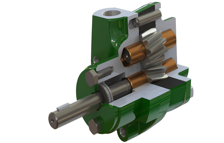
The Mechanical Principles of a gear pump for oil
The function of a high-quality oil gear pump is centered on the displacement of fluid through the rotation of meshing gears. As the gears rotate away from each other at the suction side of the pump, a vacuum is created, drawing the fluid into the expanding cavities between the gear teeth. As the gears continue their rotation, the fluid is carried around the perimeter of the pump casing toward the discharge side.
When the gear teeth mesh again at the discharge port, the fluid is forcibly expelled. Because the space between the teeth is fixed and the rotation is constant, the output remains steady and predictable. This pulse-free flow is a critical advantage for systems that require high precision and stable pressure, such as those found in automated machining centers or engine lubrication circuits.
External vs. Internal Design Configurations
Industrial applications typically categorize these components into two primary configurations: external and internal setups.
- External Configurations: These utilize two identical gears that rotate against each other. They are widely favored for high-pressure applications because they can be manufactured with extremely tight tolerances, minimizing internal fluid slippage.
- Internal Configurations: These feature a smaller gear rotating inside a larger, internally toothed gear. This design is exceptionally versatile, offering superior performance when handling higher-viscosity fluids or when the system must accommodate varying flow requirements without sacrificing volumetric efficiency.
Choosing between these configurations is a decision dictated by the viscosity of the lubricant, the required discharge pressure, and the specific footprint constraints of the machinery.
Critical Considerations for Maintaining an oil gear pump
Longevity in fluid power systems is rarely an accident; it is the result of rigorous adherence to maintenance protocols. Because the interior of an oil gear pump relies on the fluid itself to create a seal between the gear teeth and the pump housing, internal wear is a primary concern.
The Role of Lubrication and Viscosity
The fluid being pumped acts as the primary lubricant for the internal bearings and the gear faces. If the oil is contaminated with particulate matter or moisture, it can transform from a lubricant into an abrasive paste, leading to premature erosion of the housing and loss of flow capacity. Regular oil analysis—checking for metal shavings or degradation of the fluid’s additives—is the most effective way to identify internal wear before it results in a total system failure.
Preventing Cavitation and Aeration
One of the most frequent causes of premature failure in these systems is cavitation. This occurs when the suction pressure drops below the vapor pressure of the oil, causing bubbles to form. When these bubbles move to the high-pressure side of the pump and collapse, they create miniature shockwaves that can pit the metal surfaces of the gears. Operators should ensure that intake lines are clear of obstructions and that the fluid temperature remains within the specified operating range to prevent air ingestion and vapor lock.
Applications Across Diverse Industrial Sectors
The reliability of a gear pump for oil makes it an ideal choice for a variety of demanding environments. In the energy sector, these pumps are commonly used for the transfer of heavy fuel oils and the cooling of massive transformers. In the manufacturing sector, they are the heartbeat of hydraulic presses and metal-forming equipment where precise, high-pressure actuation is necessary.
Furthermore, these units are indispensable in the automotive industry. Modern combustion engines depend on precisely engineered pumps to circulate engine oil through galleries, cooling and lubricating critical components like camshafts and crankshaft bearings at high RPMs. In this context, the efficiency of the pump directly influences the overall thermal management and service life of the engine.
Selecting the Right Component for Your System
When evaluating a new or replacement pump, engineers must look beyond the basic flow rate and pressure specifications. The selection process should focus on:
- Material Compatibility: Depending on the acidity or additive package of the oil, the casing and gear materials—typically steel, bronze, or specialized cast iron—must be resistant to corrosion and chemical breakdown.
- Pressure Capability: Systems operating at extreme pressures require pumps with reinforced housings and specialized seals to prevent external leaks and internal bypass.
- Efficiency Ratings: Volumetric efficiency, which measures the ratio of actual flow to theoretical flow, is a key performance indicator. A high-efficiency pump will generate less heat during operation, which in turn reduces the energy consumption and stress on the rest of the hydraulic system.
The Future of Fluid Transfer Technology
As industrial automation continues to evolve, the integration of smart sensors into traditional pumping systems is becoming more prevalent. Modern industrial units are now being outfitted with vibration sensors and flow meters that report data back to central control systems in real time. This shift toward “predictive maintenance” allows engineers to monitor the health of an oil gear pump without having to perform invasive manual inspections.
By tracking heat signatures and motor load, operators can predict exactly when a seal needs replacement or when a bearing is beginning to degrade. This transition from reactive repairs to data-driven service is setting a new standard for reliability, ensuring that downtime becomes an anomaly rather than a standard operational risk.
Conclusion: Reliability Through Structural Integrity
The gear pump for oil is a testament to the fact that, in engineering, simplicity often delivers the highest level of performance. By maintaining the integrity of these pumps through proper filtration, thermal regulation, and careful component selection, industrial facilities can significantly improve their operational consistency.
Whether you are managing a large-scale manufacturing plant or overseeing the maintenance of heavy-duty hydraulic machinery, understanding the nuances of these systems is key to safeguarding your equipment. As you evaluate your current fluid power infrastructure, remember that the most effective way to maximize output and minimize long-term costs is to ensure that every gear pump for oil within your fleet is operating at its peak potential, free from contamination, and matched perfectly to the demands of its specific environment.